R&D Capabilities
Shaping the Future of Mobility through Innovation and Testing Excellence
Design Process
From CATIA to production
Every SSWL wheel begins as a 3D model. Our in-house design team uses CATIA V5 — the industry-standard CAD platform across global automotive — to engineer wheel assemblies from first principles, ready for FEA, prototyping and full validation.
CAE Toolchain
Industry-standard software, end-to-end.
The same software stack used by global automotive OEMs and Tier-1 wheel manufacturers — covering 3D modelling, linear and non-linear FEA, casting flow simulation and impact analysis.
CATIA V5
3D modelling & styling
NX
Design & tool engineering
NX NASTRAN
Linear FEA
LS-DYNA
Non-linear FEA & impact
VPG
Non-linear FEA
ADSTEFAN
Casting flow simulation
ANYCASTING
Casting flow simulation
AutoCAD
2D drawing
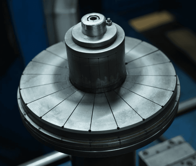
Optimized Design
Steel Passenger Car Wheel Rim – Flow Forming
To enhance efficiency and performance, the focus is on reducing wheel rim weight while maintaining structural integrity and functional requirements. This is achieved through the implementation of a variable thickness rim design, strategically identifying regions with lower influence from radial and impact loads.
Reduction in wheel weight (~5 to 8%) without compromising functional strength leads to fuel efficiency & economy of vehicle.
With flow forming process the grain structure of the rim material will be more refined leading to increase in Tensile strength.
Since flow forming operation is processed after butt welding operation, there is no adverse effect on weld ability.
Presently, SSWL is the only Wheel Supplier in India capable of producing Flow-Formed Steel Wheel Rims for Passenger Car application.
FF Rim successfully developed for European Car maker, PSA-Peugeot-Citroen.
Inside our testing lab
Real rigs, real validation — every wheel proven before it ships.
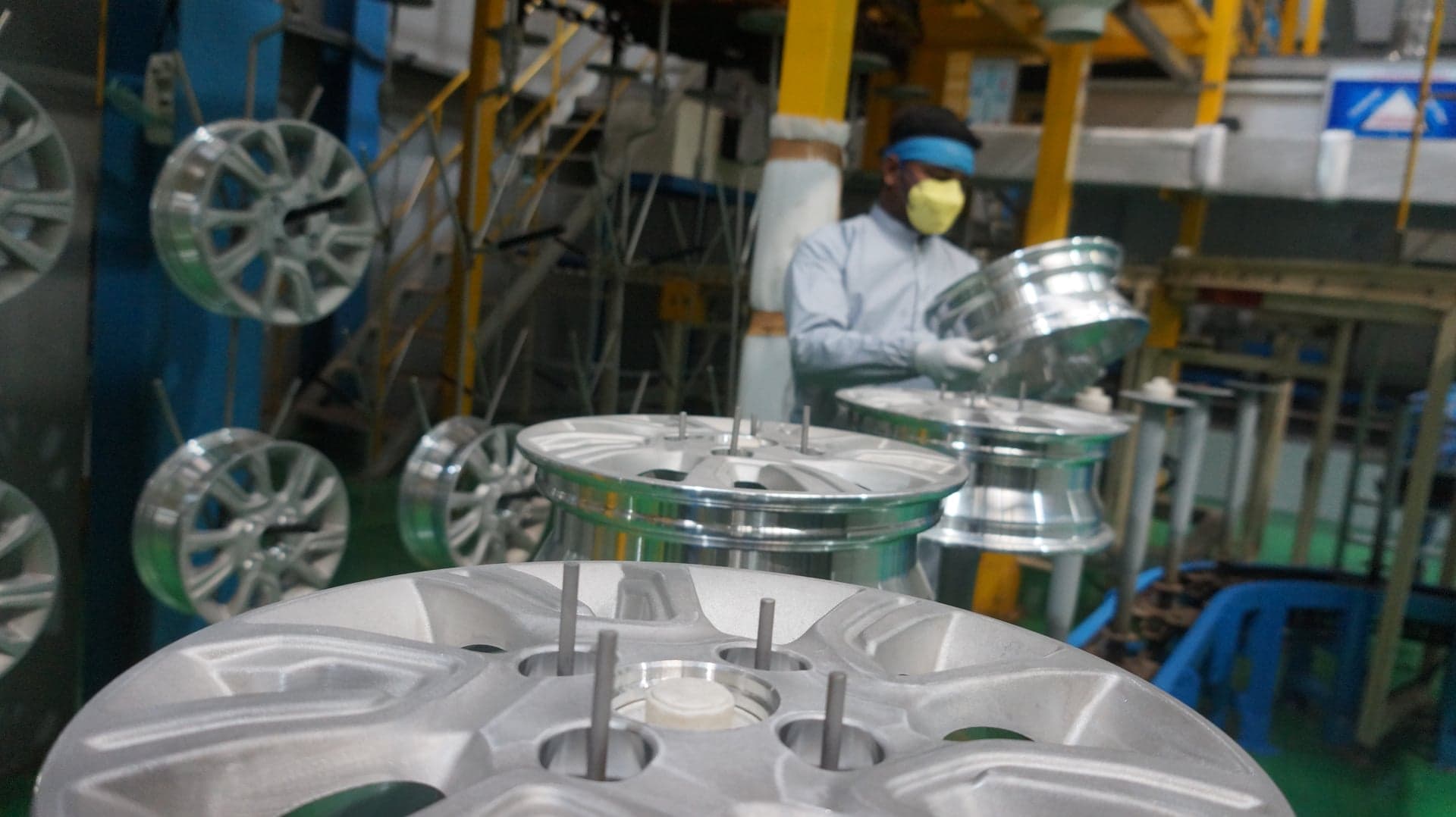
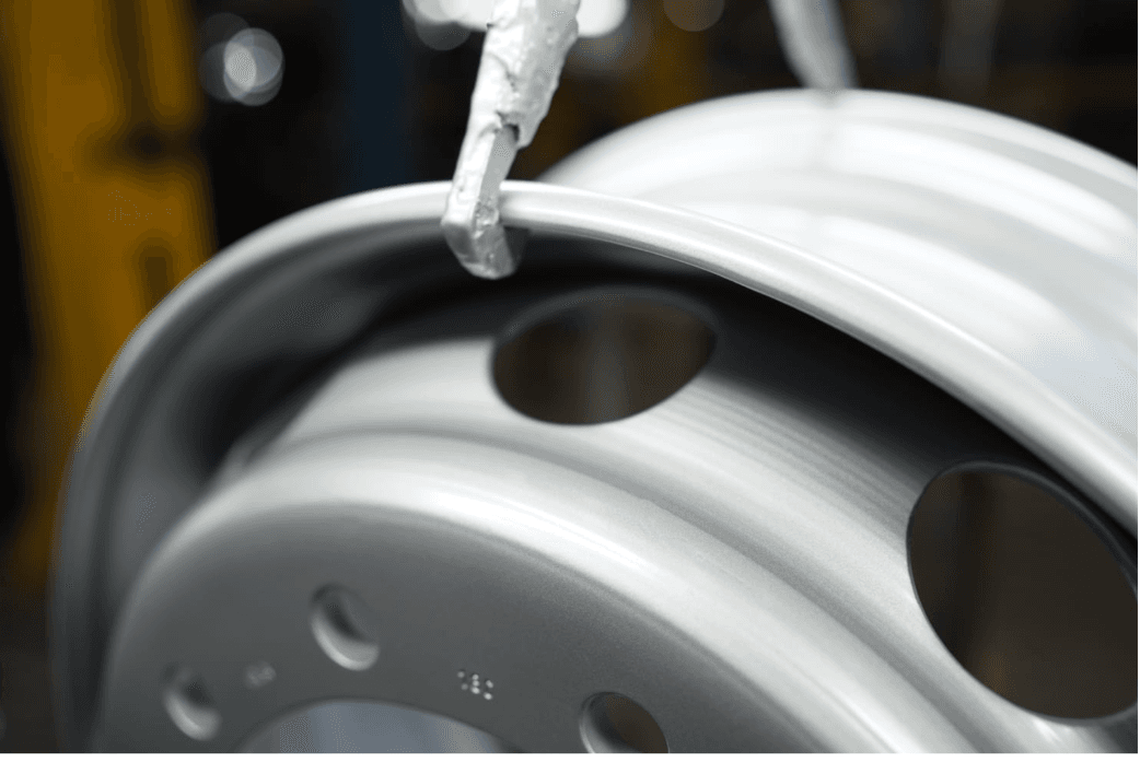
Salt Spray Validation
Corrosion resistance testing under accelerated saline exposure.
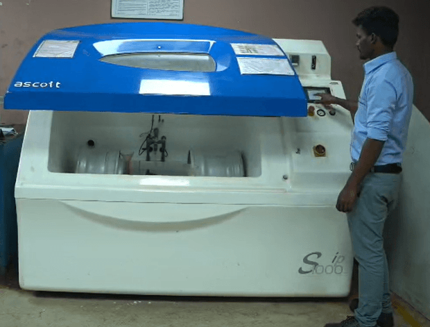
Cornering Fatigue Test
Bending-moment lifecycle test on wheels up to 38”.
Balancing
Dynamic balancing for vibration-free, high-speed performance.
Runout Inspection
Precision runout checks at micron-level tolerances.

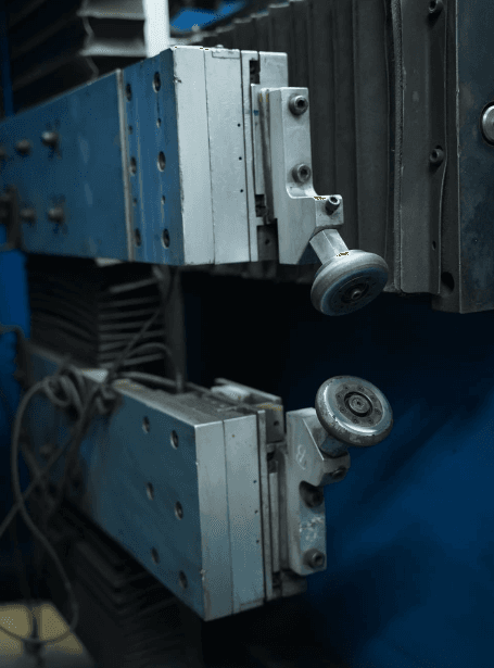
Auto Butt Welding
Automated weld integrity at the heart of every steel rim.
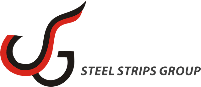
Component Validation
End-to-end validation across precision-machined assemblies.
New Product Development
Testing & Validation Capabilities
Product Design & Validation
We develop products from scratch, gathering customer requirements and delivering customized, application-specific solutions. The validation process involves FEA analysis, prototype testing, and final approval.
Radial Fatigue Test (RFT)
We operate one of India's largest RFT machines, testing wheels up to 44 inches in diameter under realistic load and speed conditions to validate performance.
Cornering Fatigue Test (CFT)
Our CFT machine tests wheels up to 38 inches in diameter, applying bending moment conditions to assess wheel strength and lifecycle durability.
Coordinate Measuring Machine (CMM)
Our CMM technology ensures that every wheel meets exact customer specifications, with micron-level inspections to detect any deviations early.
Weld Penetration Testing
We conduct weld penetration analysis using advanced microscopes to verify weld strength, ensuring safe and long-lasting wheels.
Bend Test for Butt Welding
A 180-degree bend test ensures flawless welding integrity, preventing failures during the wheel forming process.
Field/Track Testing
We collaborate with customers to conduct extensive field tests, ensuring wheels withstand real-world conditions and deliver top-notch performance in all terrains.
Test Coverage
Validated at every level of load
Fatigue, impact, NVH, stiffness and crush — every load case covered, every test mapped from component-level rigs all the way through to vehicle-level validation.
CAE Domain
Component-Level Tests
Vehicle-Level Tests
Fatigue
Component-Level
Vehicle-Level
Impact
Component-Level
Vehicle-Level
NVH
Component-Level
Vehicle-Level
Stiffness / Rigidity
Component-Level
Vehicle-Level
Crush
Component-Level
Vehicle-Level
Correlation Proof
Simulated matches real.
We don't just simulate — we validate. Every CAE model is correlated against physical test results before it's trusted to drive a program decision.
Modal Frequency
90%
correlation between CAE and physical modal test
Rim 1st-Order Resonance
374 Hz
vs ≥ 300 Hz target — measured and CAE-confirmed
Strain Gauge vs FEA Stress
Spoke window region
| Location | SGA | FEA Von-Mises | FEA Principal |
|---|---|---|---|
| Big Window — Top Surface | 78.2 MPa | 76.7 MPa | 74.5 MPa |
| Big Window — B Surface | -74.4 MPa | 76.7 MPa | 74.5 MPa |
| Small Window — Top Surface | 90.1 MPa | 84.0 MPa | 84.4 MPa |
| Small Window — B Surface | -87.2 MPa | 84.0 MPa | 84.4 MPa |
Stresses observed in FEA and Strain-Gauge analysis match within ~5% across all measurement points.
Advanced Methods
Where standard tests end, ours begin.
Beyond the regulator-mandated coverage, SSWL operates three differentiated validation methods — each adopted because real-world failure modes demanded more than standard tests could capture.
Beyond SAE J175
Wheel Crush Test + SORB Correlation
Vehicle crashes load wheels in ways the standard 13° impact test doesn't capture. SSWL has developed an in-house Wheel Crush Test correlated with the vehicle-level Small Overlap Rigid Barrier (SORB) crash test — characterising reaction force, displacement and failure modes for every program.
MATFEM, Germany
Material Damage Card for Crack Prediction
Damage card developed in partnership with MATFEM Germany — built from extensive coupon testing on actual wheel geometry. Lets FEA predict not just stress, but the actual crack initiation and propagation path. Brings physical-failure-grade accuracy to virtual validation.
TUV Certified
Bi-Axial Fatigue — Euro / AK Cycle
In-house Bi-Axial (Zwarp) test facility, TUV-certified to SAE J2562 and EUWA ES 3.23 standards. Combines RFT (radial) and CFT (lateral) loads to reproduce real-world wheel loading — accelerating 300,000 km of damage into a 10,000 km test cycle.
Validation Lab
Inside the validation lab
The physical infrastructure behind every TUV certificate — fatigue rigs, servohydraulic systems, and wheel-mounted instrumentation.
Bi-Axial Fatigue Rig
Leonardo 7008518 — Zwarp
Simulates real-world wheel loading by combining radial, axial and tilt-angle forces on a rolling drum — accelerating 300,000 km of damage into a 10,000-km test cycle.
- Drum diameter
- 1,800 mm
- Max wheel size
- Ø 1,600 × 800 mm
- Radial load max
- 250 kN
- Axial load max
- 100 kN
- Speed range
- 10 – 130 km/hr
- Standards
- SAE J2562 · EUWA ES 3.23
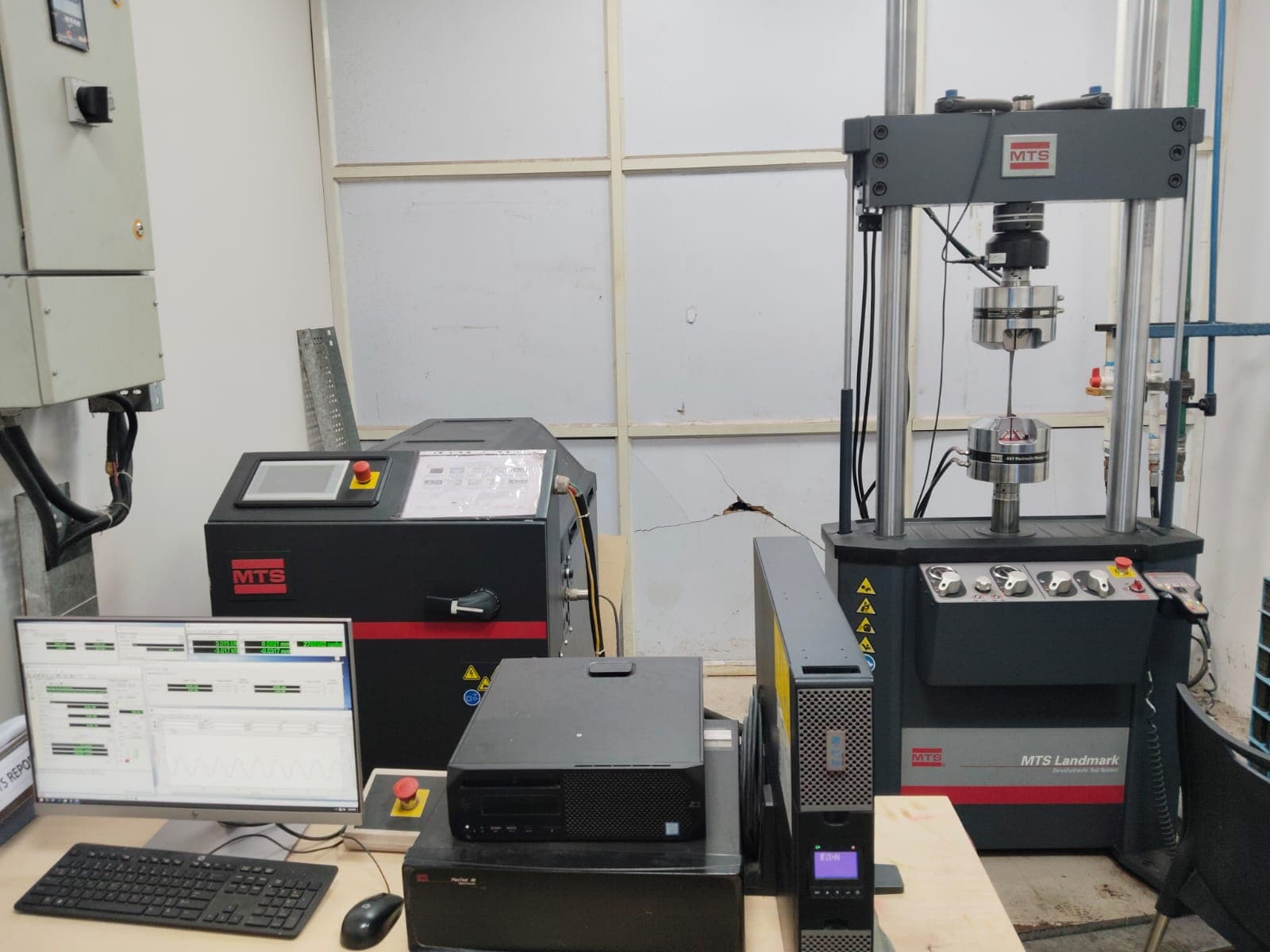
Servohydraulic
MTS Landmark Test System
Component-level fatigue and material characterisation — closed-loop hydraulic actuation with real-time waveform control.
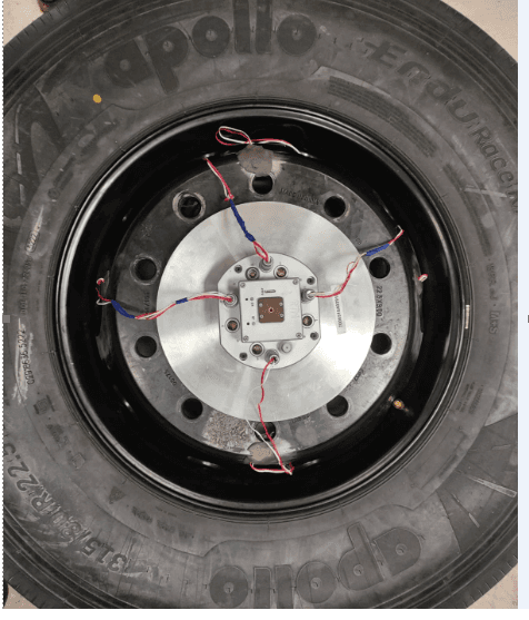
In-Wheel Instrumentation
Wheel Strain Telemetry
Hub-mounted strain gauges capture real loading during dynamic test — feeds FEA-vs-measured correlation to within ~5 %.
Shaping the Future of Mobility
At SSWL, our R&D and Testing Capabilities reflect our commitment to innovation, safety, and product excellence. By continuously pushing the boundaries of wheel manufacturing technology, we empower our customers with high-performance, reliable, and cutting-edge solutions.
Get in Touch